First, the VMR acquired in the same session needs to be created (see the BVQX Getting Started Guide for the procedure). If needed, the VMR can be brought into AC/PC or TAL space. For this demonstration it is not necessary, so we stay in native space. Close all open projects and open the VMR human.vmr.
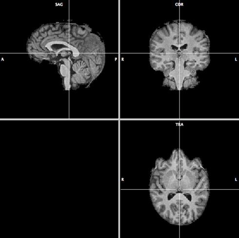
Co-registration works better if the non-brain tissue is removed in the VMR. Go to Volumes --> Segregate Brain from Head Tissue. When BrainVoyager is finished, the result should look like this:
Save the VMR as human_brain.vmr.
Go to DTI --> Coregister DMR/DWI to VMR. A menu appears with 4
tabs, Files, Source Options, Initial Alignment and Fine-Tuning
Alignment. Let’s start with the first tab:
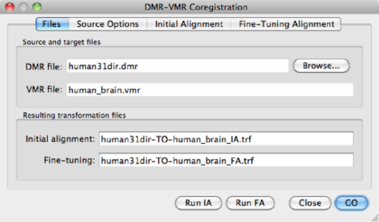
Use the Browse button to point to the DMR just created )human31dir.dmr. BV
automatically creates file names for the transformation files, i.e.
<DMRname-TO-VMRname>_IA.trf and <DMRname-TO-VMRname>_FA.trf.
In principle, one could click on Run IA and Run FA now, but let’s have a look at the important other tabs first.
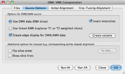
Use DMR data (DWI Slices) | Use the first volume of the DMR data for coregistration. Watch out! First volume should be b0. |
Invert intensities | Since intensities in the b0 images are inverted compared to a T1 anatomical image, this option might be used. For instance, the ventricles in a b0 are white, and on the T1 black. |
Use linked AMR | Use the AMR created from the first volume of the data for co-registration. Again, watch out! AMR should correspond to a b0 image. |
Create edge display for DMR/AMR data | Use this option for calculating edges in the AMR/DMR volume, which may help co-registration. |
Create Volume | Applies any of the settings chosen above. |
Flip Slice order | [Advanced] Use this option together with To SAG if the DMR and VMR data were acquired in different sessions. |
To SAG | See above. |
In this manual, we opt for the Use DMR data (DWI Slices), create edge
display and
invert intensities. After choosing this option, click Create Volume to
create an image similar to the one in figure 1.3.
Go to the Initial Aligment tab.
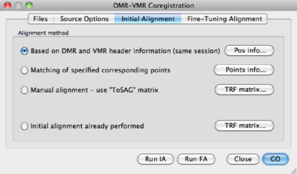
Based on DMR and VMR header information (Same session) | This is the default and easiest option. POS info shows you the header information. |
Matching of specified corresponding points | [Advanced] Do the co-registration based on user-specified landmarks. Needed when no header information is available or when the co-registration based on the header information fails. Points info shows the defined points. |
Manual alignment -- use "To SAG" matrix | [Advanced] Manual alignment, only used when automatic alignment fails. If in the Source Options a To SAG matrix was defined, it can be inspected via the TRF matrix button. |
Initial Alignment already performed | Trivial |
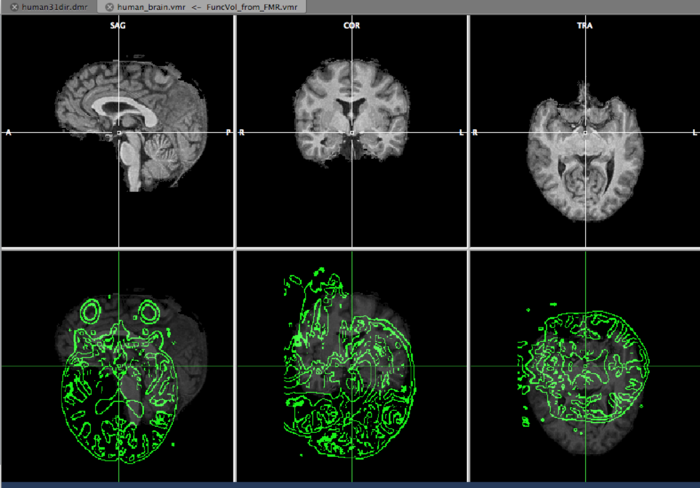
Now it’s time to hit the Run IA button. A view similar to the one below
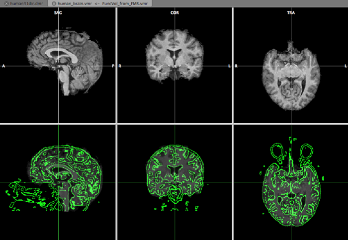
appears, and we can inspect the initial aligment using the F8 and F9 buttons on your keyboard. F9 defines the type of view and F8 toggles between the VMR and DMR. The green edges represent the DWI data.
After the initial alignment, the coregistration window has disappeared. Open it again via DTI --> Coregister DMR/DWI to VMR. Go to the Fine-Tuning Alignment tab:
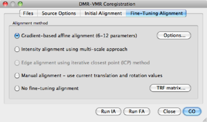
NGF based affine alignment (12 parameters) | Default option |
Intensity Alignment using multi-scale approach | Default option in BVQX < 2.0 |
Edge alignment using iterative closest point (ICP) Method | Not available |
Manual alignment - use current translation and rotation values | [Advanced], only recommended when automatic alignment fails. |
No fine-tuning alignment | Use if initial alignment is satisfactory. |
TRF matrix | shows the current transformation matrix. |
Choose the default option using a NGF approach (you might want to try out different parameters, in the Options dialog), and click Run FA. A progress bar will appear and shortly afterwards BV has finished the alignment procedure. BV has saved the transformation parameters in separate files, which are used in the next step of the analysis.