Evaluation of CBA - Part I: Assessing curvatures on a standard sphere
- Details
- Category: Cortex Based Alignment
- Last Updated: 13 April 2018
- Published: 13 April 2018
- Hits: 4338
Loading a Talairach VMR
First, we want to check the pattern of gyri and sulci before the cortex-based alignment. Here, we expect a rough, but not optimal alignment, based on the Talairach normalization.
Basically any Talairach dataset from the sample may be used as a starting point (to access the surface module):
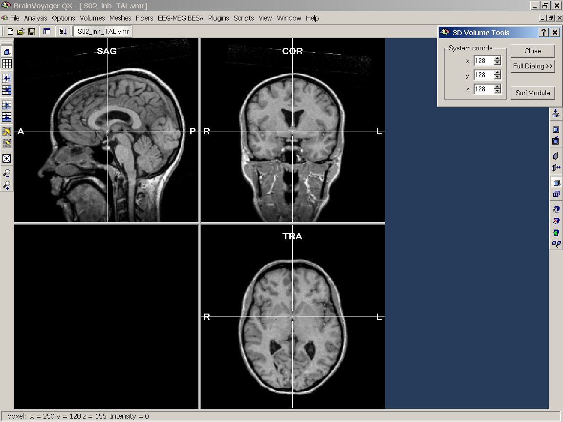
Figure 1: Sample Talairach VMR project
The standard sphere
Now, we need an object to display the surface maps on. This will be the so called standard sphere. To be able to use this dialog, we have to open a surface before. In this case, we load the reconstructed and smoothed WM-GM border of the left hemisphere of one of the subjects.
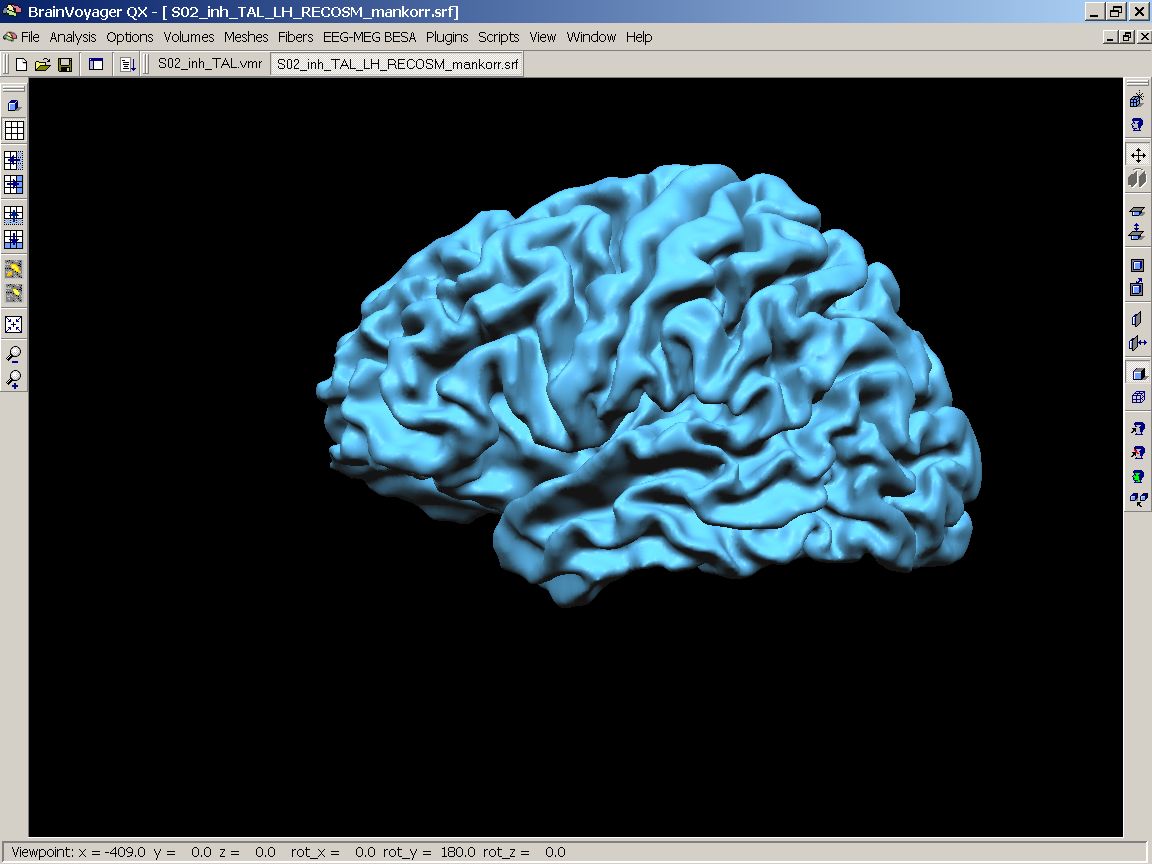
Figure 2: Sample surface mesh (SRF)
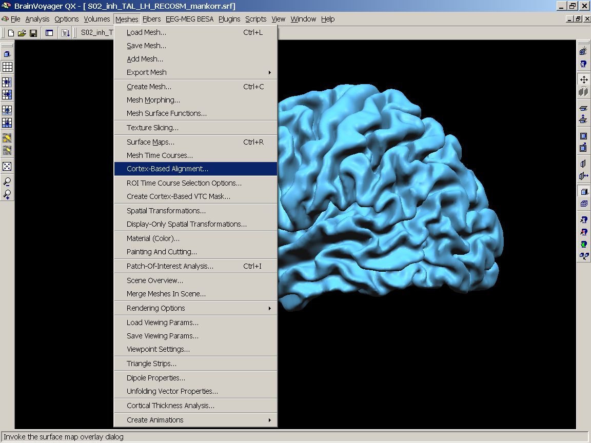
Figure 3: Meshes - Cortex based alignment menu
After the cortex-based alignment dialog has come up, we create a standard sphere by clicking the Create button on the Options tab of the diaog box. This sphere should be saved for future reference.
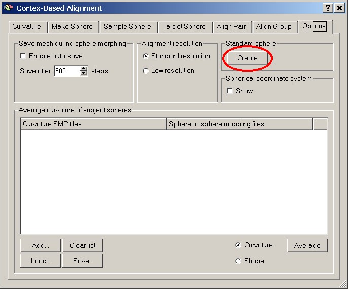
Figure 4: Create standard sphere button
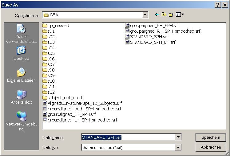
Figure 5: Save As dialog for sphere
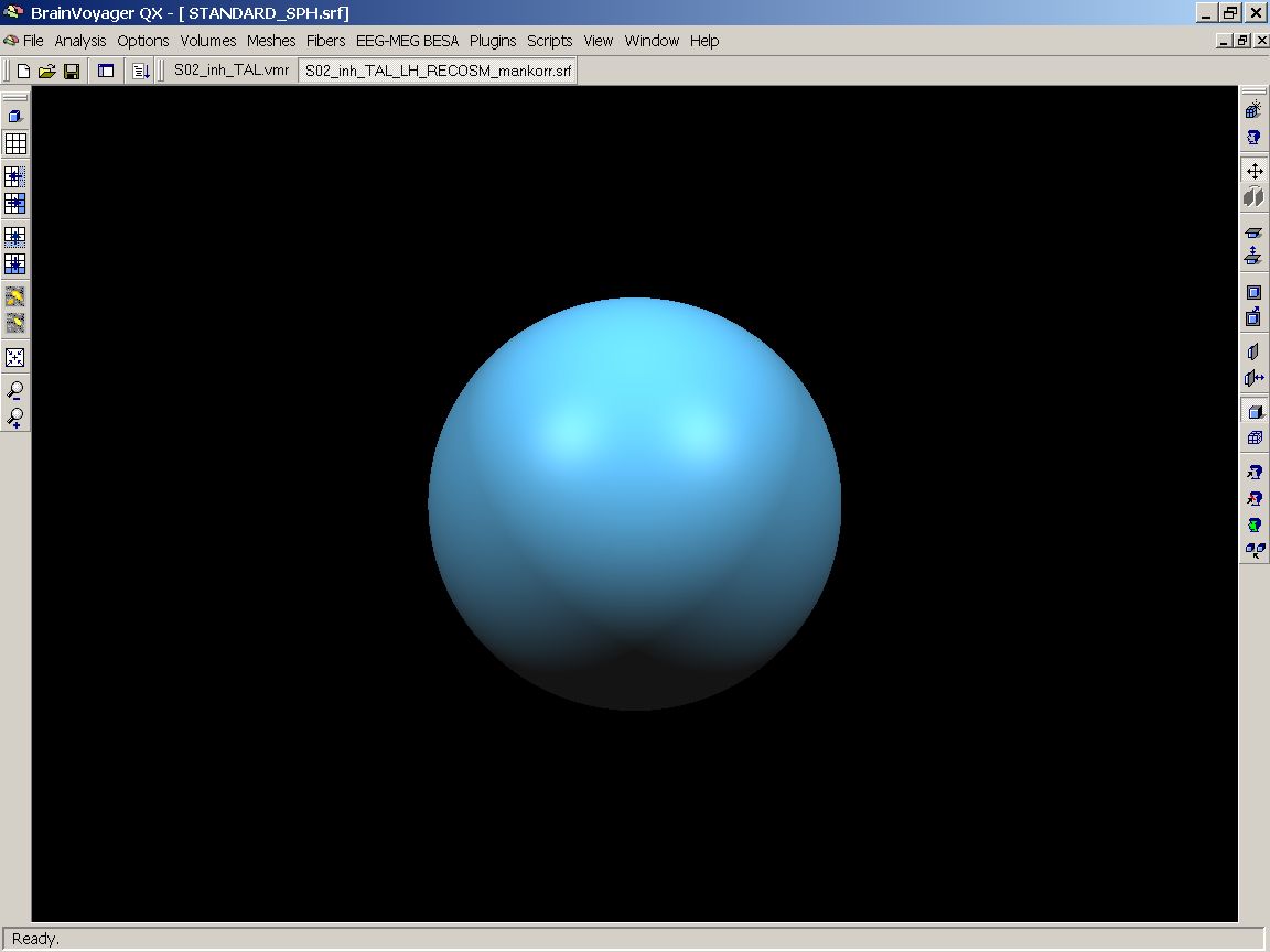
Figure 6: Standard sphere
Now, we are ready to display the surface maps created in the course of the Cortex-based alignment procedure. The maps, displaying the folding pattern of the gyri and sulci of a hemisphere, are created before the actual cortex-based alignment started, so overlaying them will provide us with a nice overview of how well a pure Talairach normalization provides a correspondence between the gyri and sulci of the different subjects cortices.
Displaying the curvature
First of all, we must now open the Surface Maps dialog and load the (in this case left) hemisphere of the first subject:
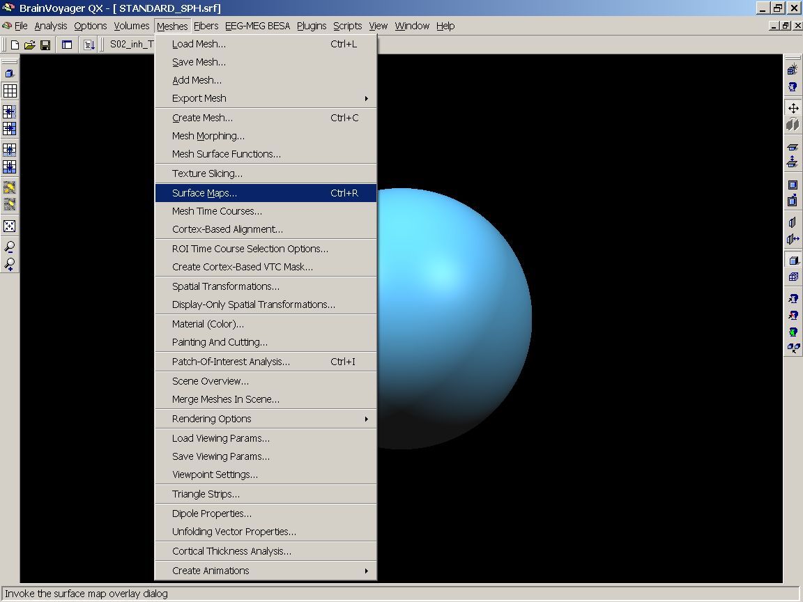
Figure 7: Surface Maps menu entry
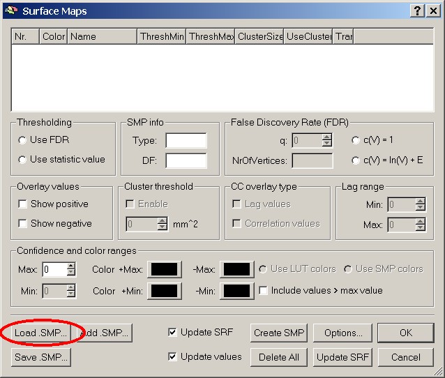
Figure 8: Load .SMP button
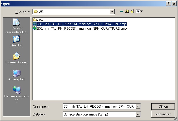 Figure 9: Loading the first SMP
It is of course important to check the overlap separately for the left and the right hemisphere. In this case, we start with the left hemisphere. On the basis of the extended filenames, it's no problem to find the proper file.
The surface map contains four different levels of smoothing (from 0 to 60 – no smoothing to severe smoothing). This enables us to check the overlay at four different levels.
To visualize a specific map, we have to mark one of the smoothing levels, e.g. sm0.
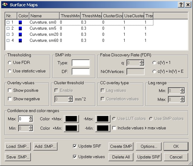
Figure 10: List of maps in SMP file
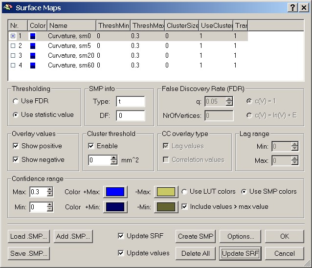
Figure 11: Selecting one of the maps
When the OK button is hit, BrainVoyager will visualize the cortical folding pattern of subject one (without smoothing applied in our example) on the standard sphere.
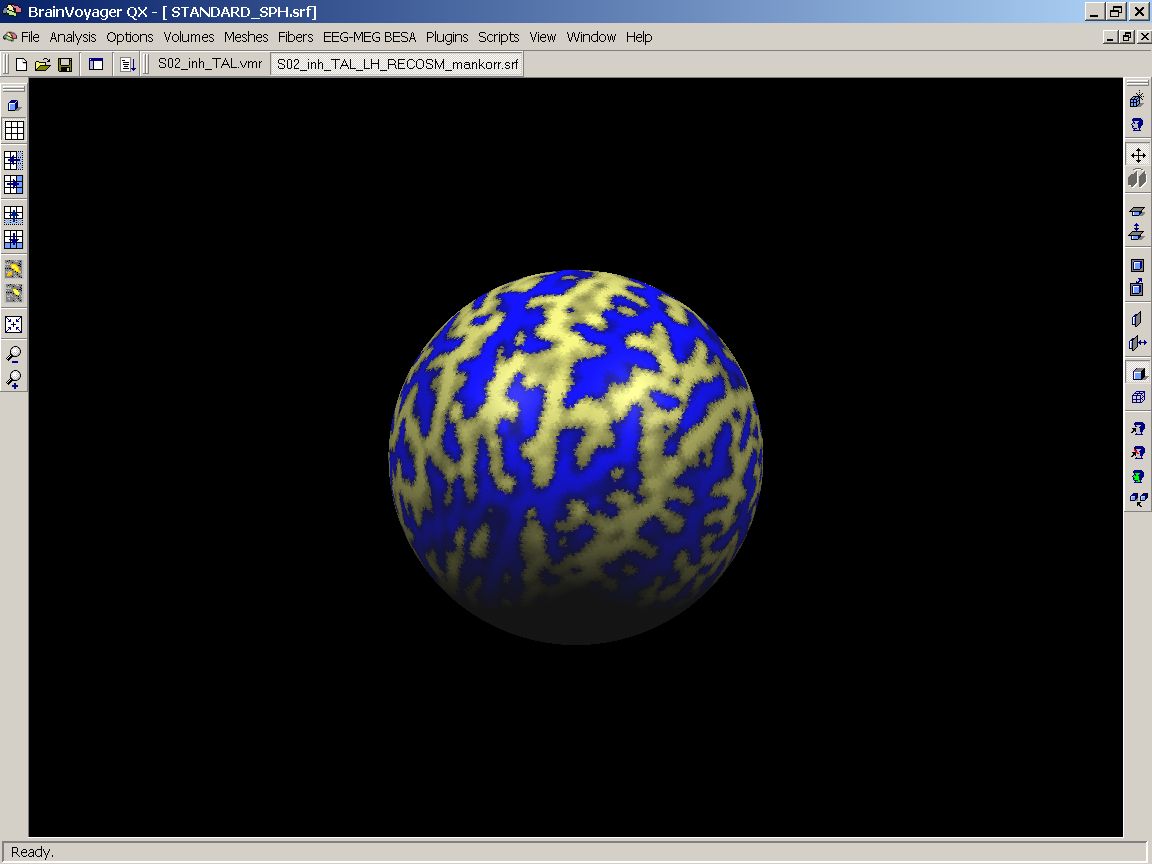
Figure 12: Visualizing the first SMP
Adding up the subjects
Now, we overlay the LH map of the second subject. To do this, we reopen the Surface maps dialog and click the Add SMP button.
Then we can visualize the pattern of gyri and sulci of both subjects' left hemispheres by marking the corresponding entries in the list:
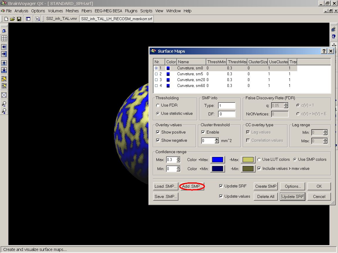
Figure 13: Add .SMP button
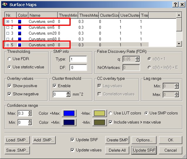
Figure 14: Selecting another subject's map
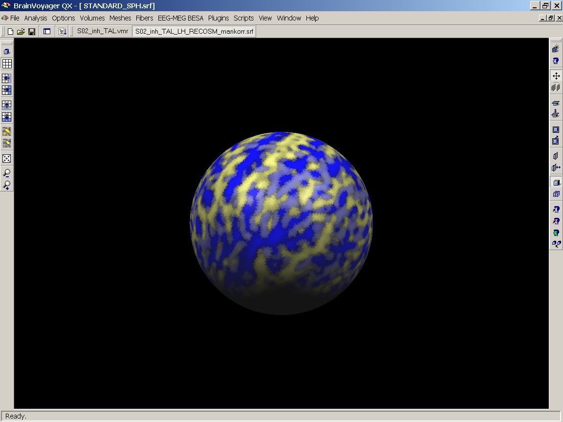
Figure 15: Two subjects' SMPs visualized
As you can see, there is some overlap, but obviously the patterns don't really match up. To give us an overview of the entire group, we redo the previous steps to add the left hemisphere maps of all the 12 subjects.
This provides us with a list of 48 entries in total (12 subjects with 4 smoothing levels for each SMP file).
It is advised to save the created surface map file for further applications.
Adding up the subjects
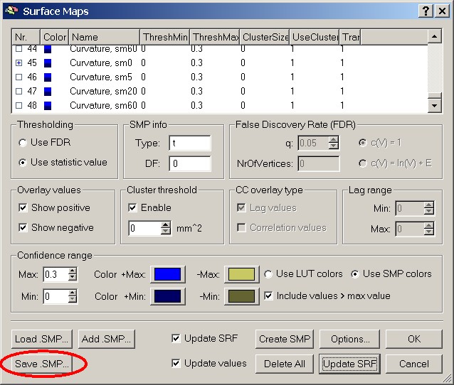
Figure 16: Save .SMP button
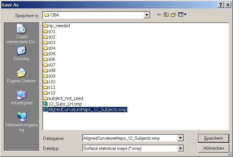
Figure 17: Save As dialog for new SMP
In the end, we have an overlay map of the folding pattern of the left hemispheres of 12 subjects. As can be nicely seen, there is a reasonable overlap of the major gyri and sulci, but still a large amout of variation, esp. in the finer structures. The mesh should equally be saved.
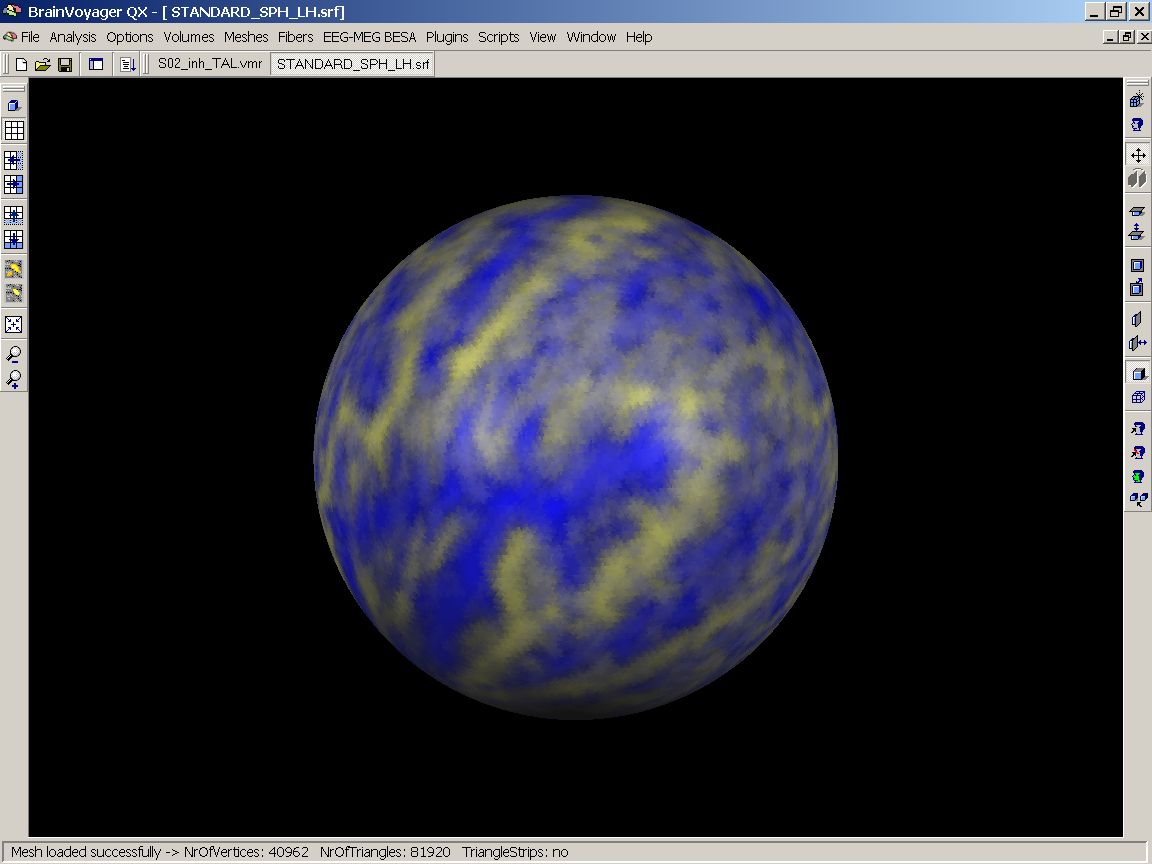
Figure 18: 12 unaligned maps on standard sphere
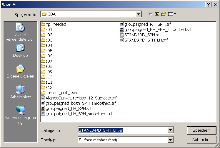
Figure 19: Save As dialog for SRF
